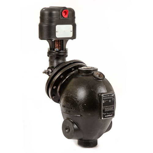
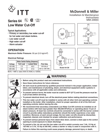
mcdonnell miller no 5 switch wiring diagram
2004 toyota Sienna Wiring Diagram Pdf. 11 Switch Used on McDonnell No.
Tpi Wiring Harness Diagram.

. 2 Single pole double break switches provided for operation at 2 different levels. 11 Switch Used on McDonnell No. Mcdonnell miller low water cut offs are specially designed to protect steam and hot water boilers from the hazards of a low water condition.
Mcdonnell miller 67 wiring diagram - Whats Wiring Diagram. Bold lines indicate action to be taken in Step shown. Using a flathead screwdriver remove the two 2 screws that secure the feeder coverBB.
1 Mercury switch 2-wire 2 Mercury switch 3-wire 3 Mercury switch 3-wire manual reset 4 Bellows assembly MI1360. Red switch terminals 1 and 2 are for burner circuit contacts terminals 3 and 4 are for the low level alarm. Series 101-A Electric Water Feeders.
Burner onelectric feed valve or alarm o f f. Porsche 968 Wiring Diagram wiring diagram is a simplified customary pictorial representation of an electrical circuit. Mcdonnell Miller 67 Wiring Diagram Gallery.
Mcdonnell Miller Wiring Diagrams Wiring Schematic Diagram Recommended installation for low water cutoff instal directy ove large st4pb fitthg outeton of using a 34 tee and reduchg bushing. McDonnell Miller is a leader in engineering and manufacturing boiler controls liquid level controls low-water cutoffs and flow switches for steam and hot water boilers in industrial commercial and building trades applications. Mcdonnell Miller No 7b Wiring Diagram.
Yes NEMA 1 4 No No No No No No No Yes 45-36 24VAC Wire Harness Connector Yes LFx024xx model only Yes 400 only Yes 400 only No No Yes PS-802-24 Yes PSE-802-24 Yes PS-852-24 No Listing Approvals UL GUIDE MBPR for Limit Controls per UL Standard 353 Limit Controls UL GUIDE MBPR7 Limit Controls Certified for Canada per. Electric Motor Wiring Diagram 220 to 110. Every wiring diagram is different from the next and they will be different from the next one.
Using a wire nut connect a wire from the neutral side of the. Keystone Rv Wiring Diagram. 150S 157S Repair Parts Snap Switches Repair Parts for 150 157 Mercury Switch Part No.
It shows the components of the circuit as simplified shapes and the capability and signal links in the middle of the devices. 5 309100 11 Switch 05 23 6 309151 11-M No. Symbols that stand for the parts in the circuit and also.
Series 5151-2 Mechanical Water FeedersLWCO. For 67 Low Water Cut-Off Installed with McDonnell Miller Series 101-A Water-Feeder For the 120V Burner120V Feeder setups. Grey lines indicate existing wiring.
Water level dropped to electric feed valve or alarm operating level. Mercury Discontinued 040707 Order No. Wiring Diagram 263 views.
Burner offelectric feed valve or alarm o n. Wiring Diagram 218 views. Wiring diagram for low water cutoff lee itch notes.
Series RS Sensors Series-RS-X-BR-1. RS-1-HP Series-RS High Pressure Remote Sensor. For Series 93193 or 94194 with 5 or 5-M Switch Wiring Diagrams NOTEThe following diagrams are provided for refer-ence onlyIf available manufacturers wiring diagrams should always be followed to connect the device being operated.
Wiring Diagram 155 views. Burner onelectric feed valve or alarm off. This switch features a two pole double break switch for operation at two different levels multi-function for alarm or valve actuation or low water cut-off.
Blocking Porsche 968 Porsche. A wiring diagram usually gives information roughly the relative twist and. 13 Boiler Control Replacement Parts B O I L E R C O N T R O L S S eris764 continued Low Water Cut-Offs.
Porsche 968 Wiring Diagram. Mcdonnell Miller No 5 Switch Wiring Diagram wiring diagram is a simplified good enough pictorial representation of an electrical circuitIt shows the components of the circuit as simplified shapes and the talent and signal associates amongst the devices. Mcdonnell miller no 5 switch wiring diagram.
BURNER 120 VAC SUPPLY 12 34 N H 101A 69 c. LWCO Wiring RB-122 The following diagrams show how to wire a RB-122 for 120 volt and 24 volt burner circuits. This control features an automatic reset with dual switches with millivolt service for low water cut off and alarm or electric water feeders.
A wiring diagram is a simple visual representation of the physical connections and physical layout of an electrical system or circuit. 5 Switch Used on 93 193 94. Series 21221 Make-Up Water Feeders.
Robinair 34988 Wiring Diagram wiring diagram is a simplified within acceptable limits pictorial representation of an electrical circuit. Wiring Diagram 27 views. Boat Rocker Switch Wiring Diagram.
A wiring diagram is a kind of schematic which utilizes abstract pictorial icons to show all the affiliations of elements in a system. 61 andll Built-in type Low Water Cut-offs. Switches For series 93 193 94 and 194 combination low water cut-offpump controllers for steam boilers.
Manufacturer shall be Bell Gossett Domestic Pump Morton Grove IL. McDonnell Miller Service Parts Catalog PARTS LIST MM-701E. Wiring layouts are composed of two things.
It shows how a electrical wires are interconnected and will also show where fixtures and components may be attached to the system. Paddle fits 8 203mm minimum duct size Two. Provides flexibility for selection of functions such as alarm actuation valve actuation control or low water cut-off control.
Wiring Diagram 26 views. 11 for Millivolt service 05 23 Series 764 model 64-hd. 5 Wiring Diagram Legends 1.
McDonnell-Miller 150 157 Repair Parts No. Mcdonnell miller 67 wiring diagram What is a Wiring Diagram. Guard dog low water cutoff wiring diagram.
It shows the components of the circuit as simplified shapes and the facility and signal connections amid the devices. McDonnell Miller s warranty is one 1 year from date. Pin On High Pressure Steam Boiler.
150 157 Repair Parts Mercury Switches No. Burner offelectric feed valve or alarm on. Water level dropped to electric feed valve or alarm operating level.
This low water cut off must be installed in series with all other limit and operating controls installed on. Wiring diagrams 2DW401 for 3 phase 2DW438 for 1 phase piping diagrams 1 DPD21-B installation and operation instructions. 11 wmanual reset 05 23 7 309200 11-MV No.
Feeder Model LWCO Model Diagram Number Page WF2-U-24 PS-802 with burner wiring harness 1 6 WF2-U-24 PS-802 with burner terminal connections 1 6 WF2-U-24 67 w24 volt burner circuit 4 7 WF2-U-24 67 w120 volt burner circuit 6 7. STEP 4 - Electrical Wiring To prevent a fire do not use this product to switch currents over 74A 13 Hp at 120 VAC or 37A 13 Hp at 240 VAC unless a starter or relay is used in conjunction with it. 61 and all Built-in type Low Water Cut-offs.
McDonnell Miller model number 5 is an automatic reset snap switch for model number 93 193 94 and 194 controls. Series 551-S Make-Up Water Feeder. INJECT CHEMICAL WATER TREATMENT BETWEEN BOILER FEED PUMPS AND BOILERS.
5 Switch Used on 93 193.

45 400 Hydrolevel Hydrolevel 45 400 Hydrolevel Safgard 400 Non Cycling Steam Primary Low Water Cutoff 24v

Mcdonnell Miller No 5 Switch Boilersupplies Com

Hfs 25 1 Dn25 Flow Switch Liquid Water Flow Paddle Control Switch Spdt Contacts 6 380v Amazon Com Industrial Scientific

Mcdonnell Miller No 5 Switch Boilersupplies Com

Space Shuttle Cockpit Layout Google Search Spaceship Interior Cockpit Space Shuttle

Model 5 Boiler Cleaver Manualzz
Mcdonnell Miller No 5 Switch Boilersupplies Com

Compilado De Kits De Reparacion Mcdonell And Miller Pdf Switch Water Heating
Franklin Electric Franklin Electric 5800060100 Pumptec Plus Motor Protection Device 230v 1ph 1 2 5 Hp Fec58000601

Wiring An Import 5 Way Switch Guitar Pickups Electric Guitar Stratocaster Guitar
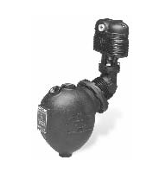
162300 Mcdonnell Miller Lwco Model 93 National Pump Supply

5 Way Switches Explained Guitar Pickups Electric Guitar Pickups Guitar Diy

On Off Switch Led Rocker Switch Wiring Diagrams Oznium Boat Wiring Automotive Repair Electricity

5 Wire Door Lock Actuator Wiring Diagram Wire Center Best Of Power Door Locks Electrical Wiring Diagram Car Door Lock
